LS1 LS2 LS6 etc series coils

Discuss which Sensors work best with these ECUs and share how you are using inputs and outputs
stevieturbo
Posts: 3588
Joined: Tue Aug 02, 2011 12:08 pm
ECU Model: No ECU
Location: Norn Iron

LS1 LS2 LS6 etc series coils

Post by stevieturbo »

Only doing this after a query via email about how to run these off a P8Pro.

I dont have all the info, but have some.

Quoting Marcos's post from the pullup resistor thread

MarcoV6T wrote:I guess you're talking about amplified coils.
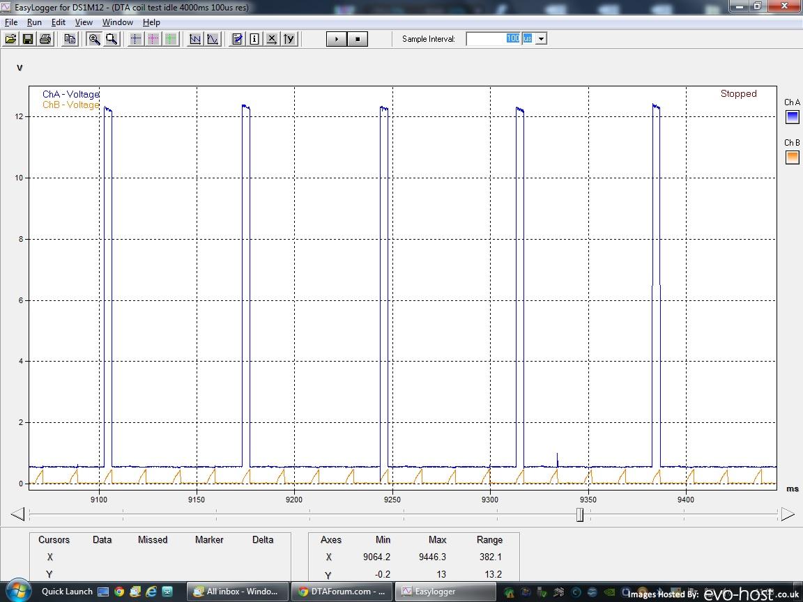
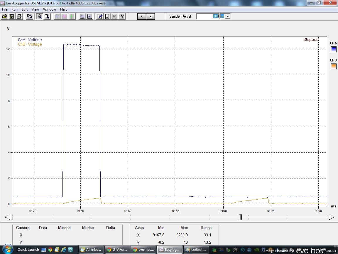
The P8, opposed to the S- series, does not have internal pull-up resistors on the coil outputs, meaning that the outputs are floating when not active(off). As most amplified coils need a positive signal to fire them, you need a pull-up on the DTA coil output, and reverse the action.

Thus when not firing the coils, the outputs need to be grounded(on), when firing a coil the dedicated output turns off, and the pull-up resistor fires the coil.

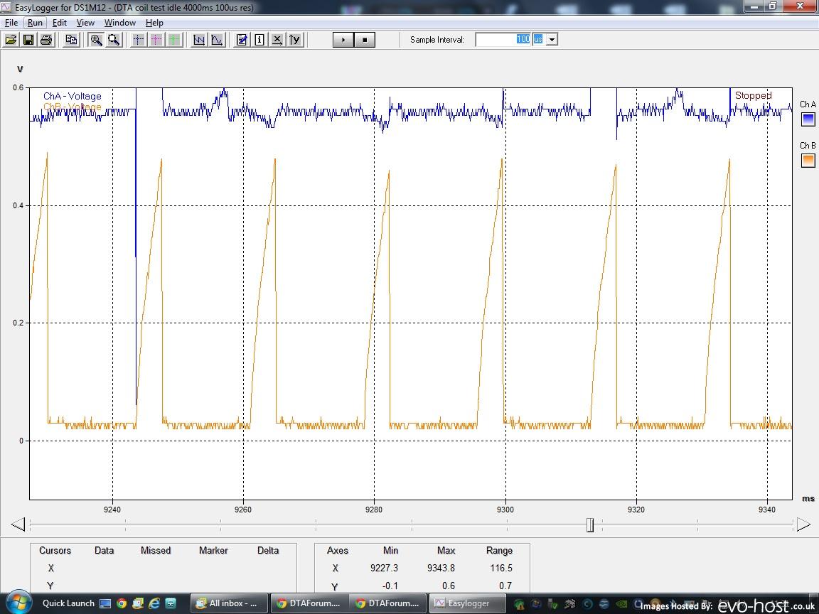
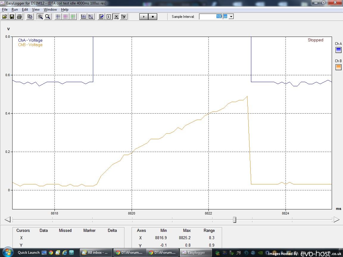
A good starting point for a pull-up resistor would be 1K, or less. the smaller the resistor, the faster the switching time, but also the more heat it will produce. You'll also notice that when the DTA is configured for amplified coils, the case heats-up when the engine is not running.

Most coils do handle 12V on the trigger, but if it can't, then wire the pull-up one side on the +5V output(or use a resistor divider from +12V), and the other to the output.
stevieturbo
Posts: 3588
Joined: Tue Aug 02, 2011 12:08 pm
ECU Model: No ECU
Location: Norn Iron

Re: LS1 LS2 LS6 etc series coils

Post by stevieturbo »

The only thing I have to add to this, is how the S series does it.

On testing, the coils will start to charge when the ecu applies 12v to the coil trigger wire. I assume this is actually a removal of ground though. Same odds

The coil then fires when the 12v is removed and the coil trigger is grounded. I think normally these operate on a 5v basis, but DTA seems to just throw 12v at them and they work just fine at that ( actually measured about 12.5v )

So I assume any pullup resistor would go between the DTA P8Pro coil output and 12v. I hope Marcos or others can confirm that is correct.
And again I think this would be easiest done at or near the coil itself from a wiring perspective, as each and every coil would need done ?

On testing with dwell at 4300us, each coil seems to pull at 5A current. I am using the early LS1 coils, with the white/cream epoxy backing. Whether later or different versions draw more current, I cant say.
This test was only conducted at idle

As I run my car in twin spark mode, ie 2 coils always firing and charging together, this would see a 10A current draw on the power wiring to the coils.

Although strangely...if my scope is right.

At idle my charge time only seems to measure about 1600us ( ie 1.6ms ) Odd, as that's pretty much exactly half of my requested dwell time.
stevieturbo
Posts: 3588
Joined: Tue Aug 02, 2011 12:08 pm
ECU Model: No ECU
Location: Norn Iron

Re: LS1 LS2 LS6 etc series coils

Post by stevieturbo »

Re Dwell...there is the possibility I havent a fucking clue about this scope :D

On coil test it reads fine, but looking back at the earlier test, it reads far more !!

The axis says ms at the bottom...but now it doesnt add up !
stevieturbo
Posts: 3588
Joined: Tue Aug 02, 2011 12:08 pm
ECU Model: No ECU
Location: Norn Iron

Re: LS1 LS2 LS6 etc series coils

Post by stevieturbo »

Just to add to this, Ive been informed that the S80 uses an internal pullup of 1kOhms
Wally
Posts: 64
Joined: Wed Aug 10, 2011 10:10 am
ECU Model: S80 Pro
Firmware Version: 51
Location: South Lakes, UK

Re: LS1 LS2 LS6 etc series coils

Post by Wally »

What sort of scope are you using?

Wally
stevieturbo
Posts: 3588
Joined: Tue Aug 02, 2011 12:08 pm
ECU Model: No ECU
Location: Norn Iron

Re: LS1 LS2 LS6 etc series coils

Post by stevieturbo »

edited and redirected. as it's more relevant


viewtopic.php?f=7&t=588&p=5983#p5983
stevieturbo
Posts: 3588
Joined: Tue Aug 02, 2011 12:08 pm
ECU Model: No ECU
Location: Norn Iron

Re: LS1 LS2 LS6 etc series coils

Post by stevieturbo »

But may as well post some here lol

Just a cheapish USB Stingray scope.

http://www.easysync-ltd.com/product/520/ds1m12.html

I think JonK on here had another brand of scope, his looked a little better. Ultimately the hardware probably doesnt matter so much as the software interface. The Stingray is just ok.
It has a lab style scope software, or a logging software. Pity the two werent combined though.

So generally the logging is best for this sort of stuff.

Couple of screenshots of the coil test at 4000us, engine running at idle.

Image

Zoomed in more. Blue trace is the DTA ecu trigger. Orange is the Hantek current clamp ( £42 egay ). Only took a few days to get here, and was much better quality than I had expected.
http://www.ebay.co.uk/itm/310649301150? ... 1438.l2649

Blue trace is just on a single coil/ecu trigger. The current clamp was on the 12v feed to all 4 on that bank hence there are 4 current draws each time in between the coil trigger.


It outputs 1mv per 10mA so the actual voltage seen is quite lo5, circa 0.5v ie 5A
The software wont allow a dual scale, so that bit is annoying. But you can re-scale either to zoom in quite easily, but one trace would then go off screen.

Image
stevieturbo
Posts: 3588
Joined: Tue Aug 02, 2011 12:08 pm
ECU Model: No ECU
Location: Norn Iron

Re: LS1 LS2 LS6 etc series coils

Post by stevieturbo »

Coil current draw zoomed in. 0 to 0.6v scale. ie 0 to 6Amps current in this case. on the 12v feed to the left bank of coils.

Image

And again closed, 0-0.8v scale.

You can still see the trigger occuring in blue. And the coil charging. 4000us dwell test engine running at idle, and it seems to maintain this according to my measurements ( so they maybe work this time lol )

Image
MarcoV6T
Posts: 101
Joined: Tue Jul 26, 2011 12:20 pm
ECU Model: S80 Pro
Firmware Version: 58

Re: LS1 LS2 LS6 etc series coils

Post by MarcoV6T »

stevieturbo wrote:So I assume any pullup resistor would go between the DTA P8Pro coil output and 12v. I hope Marcos or others can confirm that is correct.
And again I think this would be easiest done at or near the coil itself from a wiring perspective, as each and every coil would need done ?
Yes, although I installed the resistors inside the P8, back at the time.
stevieturbo wrote:At idle my charge time only seems to measure about 1600us ( ie 1.6ms ) Odd, as that's pretty much exactly half of my requested dwell time.
I know with the S-series, at idle the dwell is less than maximum, you can see the actual dwell in the diagnostic window, if I'm not mistaken.
stevieturbo
Posts: 3588
Joined: Tue Aug 02, 2011 12:08 pm
ECU Model: No ECU
Location: Norn Iron

Re: LS1 LS2 LS6 etc series coils

Post by stevieturbo »

See above re-dwell.

Really dont know what was going on there, it must be a scope issue. Ive screenshots where dwell is 1.6ms, and the same log viewed later that day is nearer 10ms !!

All other tests later that day seem to work almost as expected. With the exception perhaps of the 5ms test, dwell didnt seem to go much over 4.3ms on the scope, although current draw was higher than the 4ms test.

I scoped some of the D585 heat sink coils on a friends car with AEM yesterday. That ecu triggers via 5v, and at 5ms dwell they seemed to draw about 8A current.


So I'd say a higher value of pullup resistor would do no harm, it would just lessen the trigger voltage at the oil. But they normally work off 5v anyway, so the 12v the DTA is allowing is much higher, but hasnt had any negative effects on my coils over several years.
Post Reply